This is diy can be applied on other cars as well following the same steps and using the correct chipset !
I want to start by saying the reason I chipped my ECU was to use my P28 to run my D15B setup more efficiently. For those of you who consider chipping your ECU to run your forced induction or after-market internal setups consider the price of a professional dyno tuning session. Base Maps are ONLY good for driving your car to a tuning shop and delicately at that. Chipping your ECU for performance gains from a lightly modified setup(such as intake, or exhaust systems) would only be achieved from a good tune, and then the gains would be out-weighed by the cost. The best idea is to figure out all the components you want in your setup, get it all together, install it, and then get it tuned, as any major change to a setup will require you to pay for another tuning session.
What Youll need,
OBD-I Chipping kit from Xenocron
HondaLog Datalogging cable from Xenocron
A phillips screwdriver
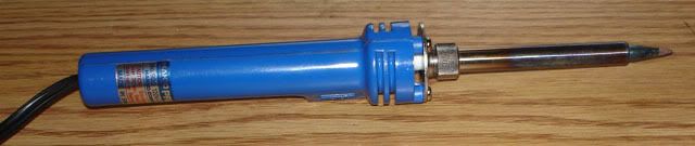
Soldering iron I used a 20/130watt
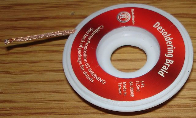
Some desoldering braid radio shack has it for about $4
Step 1, Preparation
Time to crack it open...
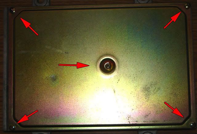
There are 5 screws on the top side of the ECU, remove them.
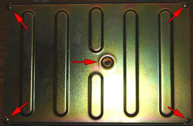
There are also 5 on the bottom.
*Optional
This is optional since its not necessary to remove the board from the casing. However in my opinion removing the board made areas more accessible.
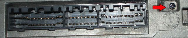
This screw here holds a component to the case for heat dispersion. You can not remove the board from the casing without first removing this screw and the small bracket it screws into.
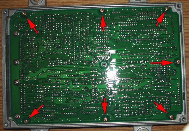
Now you can remove the board from the casing by unscrewing these 7 screws.
*
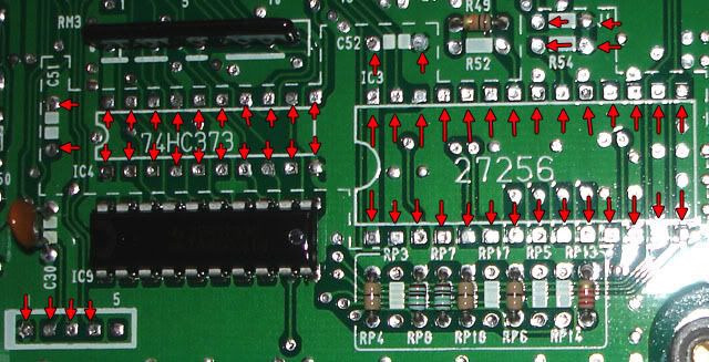
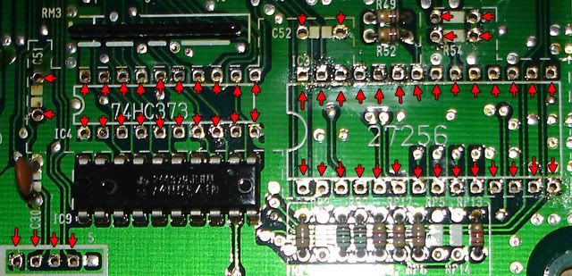
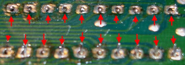
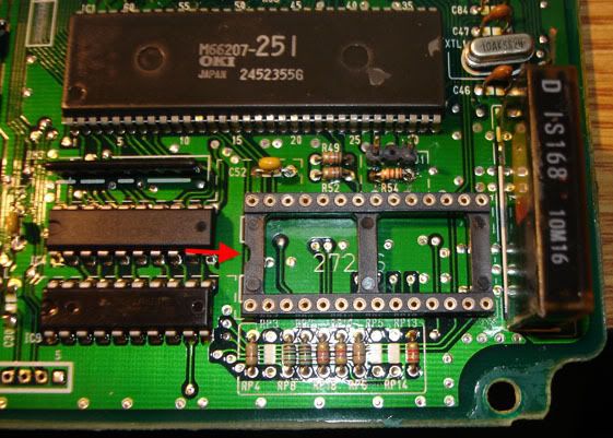
With the board facing right side up and the plugs to the left, you can see the area where the chip components will be installed in the lower right hand corner. The 60 points Ive outlined need to be desoldered.
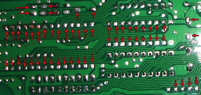
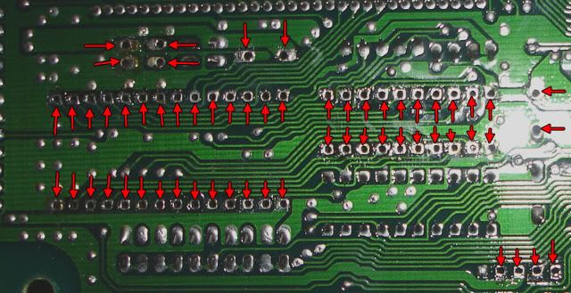
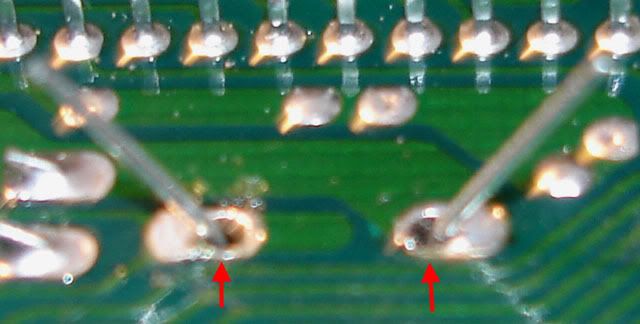
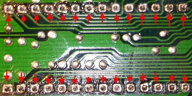
These are the same points but viewed from the bottom of the board. Sometimes its easier to get to a point from here.
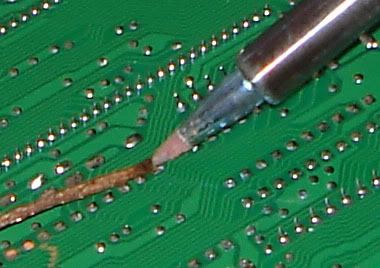
to desolder just place the end of the braid on the point and the soldering iron tip directly over it and press down. The solder will be sucked up into the braid like a wick. Once youve cleared the solder from the point youll be able to see a hole through the board. After the solder has been absorbed into the braid cut the end off containing the solder. Note: Most of the points contain enough solder to cover about 1/2" of the braid.
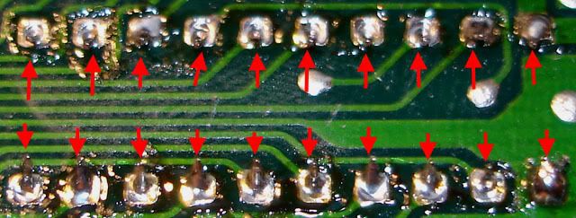
This is a top view of the points after theyve been desoldered.
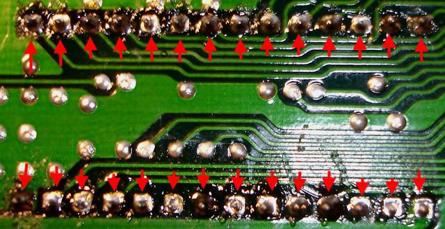
Again the points from below after desoldering.
Step 2, Assembly
Here Comes the fun part...
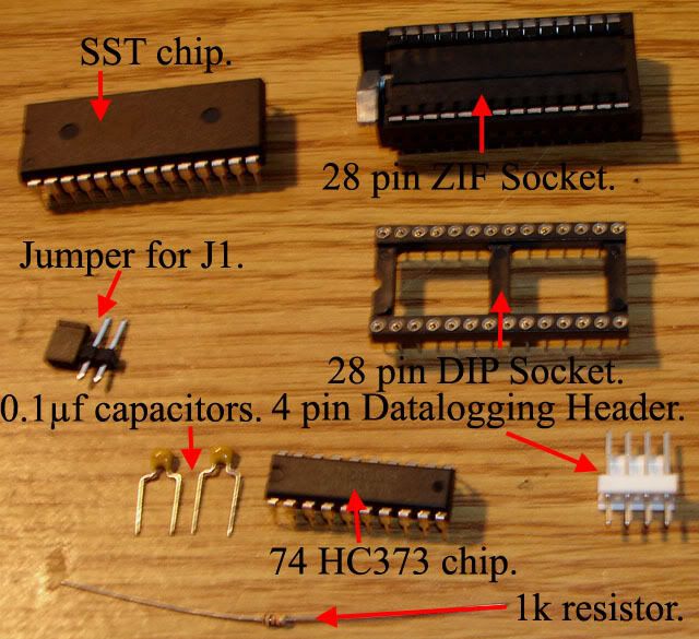
This is what comes in the Chipping Kit. If you intend on adding datalogging use the header that comes with the HondaLog kit, Its much better. *I also fabricated my own jumper for J1 since the 2 PIN one that comes with the kit has to be bent in order to align with the soldering points and then i couldnt imagine trying to solder it. I just got a spare 3 PIN header(donated from an old sound card) and removed the middle pin. For the jumper i used a 3 PIN computer case power LED connector(donated from an old case). I just soldered the 2 wires together and pushed the splice down in the middle empty pin bay.*
First well install this capacitor Just push it into place...
and bend the leads outwards to hold in place for soldering.
Once Soldered clip the excess lead wires off and it should look like this
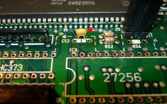
Next Well install this capacitor just the same as the last.
Bend, Solder, and clip as before.
Next Comes the Resistor. Bend the leads inwards towards the resistor and push into place. I installed it with the gold stripe towards the left like all the other resistors on the board, Im sure this is optional.

Once again bend the leads outwards to keep it in place.
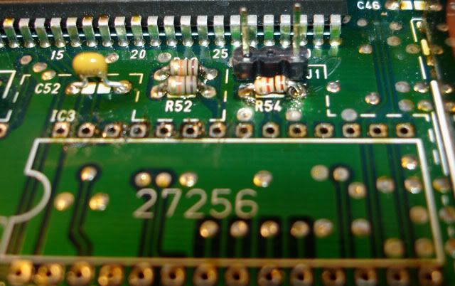
Once soldered clip the leads.
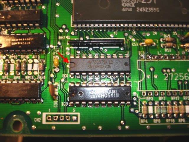
Next we have the 74 HC373 Chip. Just drop it into place making sure to align the side with the "U" indentation with the White outline on the board.
Once you have the leads through the holes bend them slightly inwards to secure the chip while soldering.
Picture post soldering.
Next We can move onto the 28 Pin Dip Socket. Just drop it into place aligning the "U" indentation with the white outline on the board.
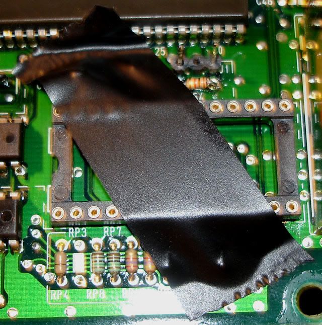
Some electrical tape will secure it to the board while soldering.
solder all 28 of these points...
...and it should look something like this.
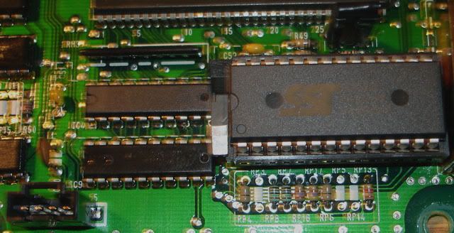
Now you can press the 28 PIN ZIF socket onto the DIP Socket. Then flip the lock up, place the SST Chip (with the "U" indentation pointing left) onto the ZIF socket and flip the lock down to secure it.
Step 3, Datalogging
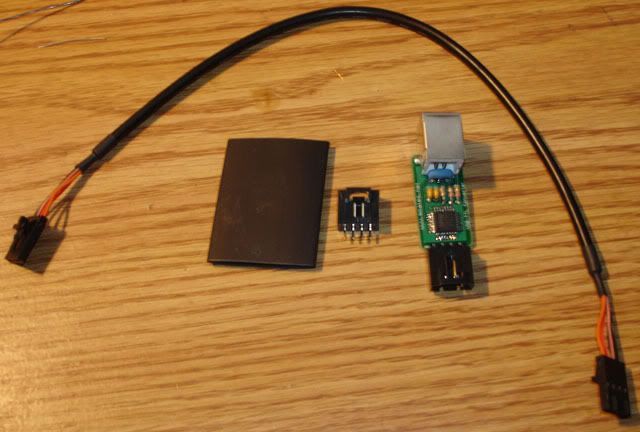
Heres What comes with the HondaLog Kit(USB cord not pictured). As you can see the header is designed for the cable it comes with. It has a nice locking feature which the chipping kit header does not. You can slip the USB board into the piece of shrink-wrap and heat it with a lighter to insulate the board.
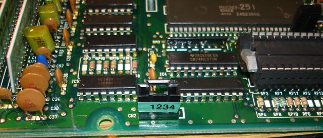
Place the header onto the board aligning points 1-4 as indicated by the helpful sticker on the header.
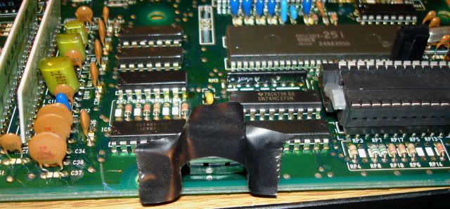
Secure the header to the board with some electrical tape for soldering.
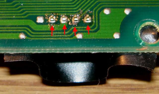
Solder these 4 points.
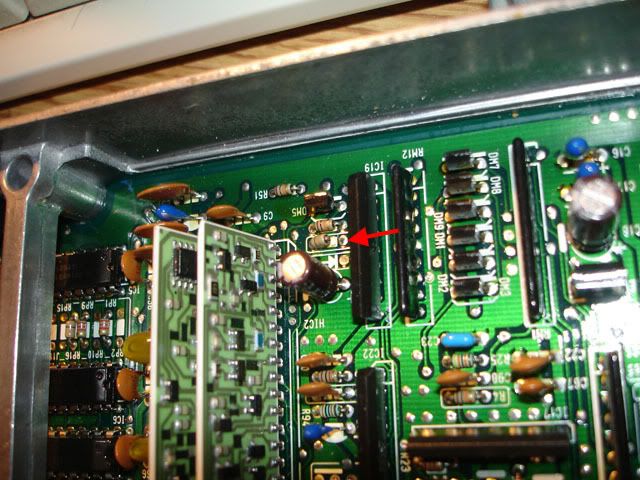
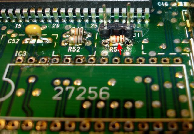
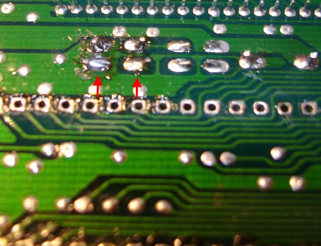
Now if youre going to use uberdata to log this step is not required. For everything else you will have to break this resistors connection. I just cut one side of the resistor with a razor blade and lifted it slightly.
All Finished!
Now youre ready to burn a map onto the chip and start tuning.
I want to start by saying the reason I chipped my ECU was to use my P28 to run my D15B setup more efficiently. For those of you who consider chipping your ECU to run your forced induction or after-market internal setups consider the price of a professional dyno tuning session. Base Maps are ONLY good for driving your car to a tuning shop and delicately at that. Chipping your ECU for performance gains from a lightly modified setup(such as intake, or exhaust systems) would only be achieved from a good tune, and then the gains would be out-weighed by the cost. The best idea is to figure out all the components you want in your setup, get it all together, install it, and then get it tuned, as any major change to a setup will require you to pay for another tuning session.
What Youll need,
OBD-I Chipping kit from Xenocron
HondaLog Datalogging cable from Xenocron
A phillips screwdriver
Soldering iron I used a 20/130watt
Some desoldering braid radio shack has it for about $4
Step 1, Preparation
Time to crack it open...
There are 5 screws on the top side of the ECU, remove them.
There are also 5 on the bottom.
*Optional
This is optional since its not necessary to remove the board from the casing. However in my opinion removing the board made areas more accessible.
This screw here holds a component to the case for heat dispersion. You can not remove the board from the casing without first removing this screw and the small bracket it screws into.
Now you can remove the board from the casing by unscrewing these 7 screws.
*
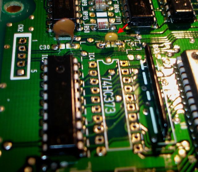
With the board facing right side up and the plugs to the left, you can see the area where the chip components will be installed in the lower right hand corner. The 60 points Ive outlined need to be desoldered.
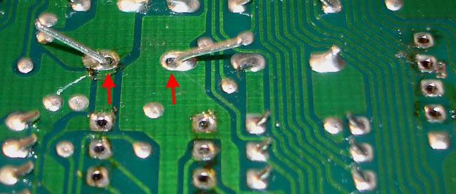
These are the same points but viewed from the bottom of the board. Sometimes its easier to get to a point from here.
to desolder just place the end of the braid on the point and the soldering iron tip directly over it and press down. The solder will be sucked up into the braid like a wick. Once youve cleared the solder from the point youll be able to see a hole through the board. After the solder has been absorbed into the braid cut the end off containing the solder. Note: Most of the points contain enough solder to cover about 1/2" of the braid.
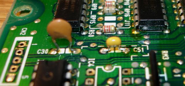
This is a top view of the points after theyve been desoldered.
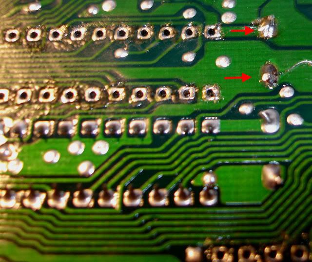
Again the points from below after desoldering.
Step 2, Assembly
Here Comes the fun part...
This is what comes in the Chipping Kit. If you intend on adding datalogging use the header that comes with the HondaLog kit, Its much better. *I also fabricated my own jumper for J1 since the 2 PIN one that comes with the kit has to be bent in order to align with the soldering points and then i couldnt imagine trying to solder it. I just got a spare 3 PIN header(donated from an old sound card) and removed the middle pin. For the jumper i used a 3 PIN computer case power LED connector(donated from an old case). I just soldered the 2 wires together and pushed the splice down in the middle empty pin bay.*
First well install this capacitor Just push it into place...
and bend the leads outwards to hold in place for soldering.
Once Soldered clip the excess lead wires off and it should look like this
Next Well install this capacitor just the same as the last.
Bend, Solder, and clip as before.
Next Comes the Resistor. Bend the leads inwards towards the resistor and push into place. I installed it with the gold stripe towards the left like all the other resistors on the board, Im sure this is optional.
Once again bend the leads outwards to keep it in place.
Once soldered clip the leads.
Next we have the 74 HC373 Chip. Just drop it into place making sure to align the side with the "U" indentation with the White outline on the board.
Once you have the leads through the holes bend them slightly inwards to secure the chip while soldering.
Picture post soldering.
Next We can move onto the 28 Pin Dip Socket. Just drop it into place aligning the "U" indentation with the white outline on the board.
Some electrical tape will secure it to the board while soldering.
solder all 28 of these points...
...and it should look something like this.
Now you can press the 28 PIN ZIF socket onto the DIP Socket. Then flip the lock up, place the SST Chip (with the "U" indentation pointing left) onto the ZIF socket and flip the lock down to secure it.
Step 3, Datalogging
Heres What comes with the HondaLog Kit(USB cord not pictured). As you can see the header is designed for the cable it comes with. It has a nice locking feature which the chipping kit header does not. You can slip the USB board into the piece of shrink-wrap and heat it with a lighter to insulate the board.
Place the header onto the board aligning points 1-4 as indicated by the helpful sticker on the header.
Secure the header to the board with some electrical tape for soldering.
Solder these 4 points.
Now if youre going to use uberdata to log this step is not required. For everything else you will have to break this resistors connection. I just cut one side of the resistor with a razor blade and lifted it slightly.
All Finished!
Now youre ready to burn a map onto the chip and start tuning.


0 comments:
Post a Comment